Administrators must nomininate which printers are available for use with Web Print. Smaller organizations may wish to make all printers available. Larger organizations may wish to restrict to a subset, e.g. limiting access to printers located in public areas. A printer may be enabled for use with web print via → → → .
Tip
To easily enable all printers for use with Web Print:
Select Enable Web Print functionality on the [Template printer].
Copy the setting to all other printers using Copy settings from printer to printer.
General Web Print configuration settings can be found in the admin interface at → → .
| Setting | Description |
|---|---|
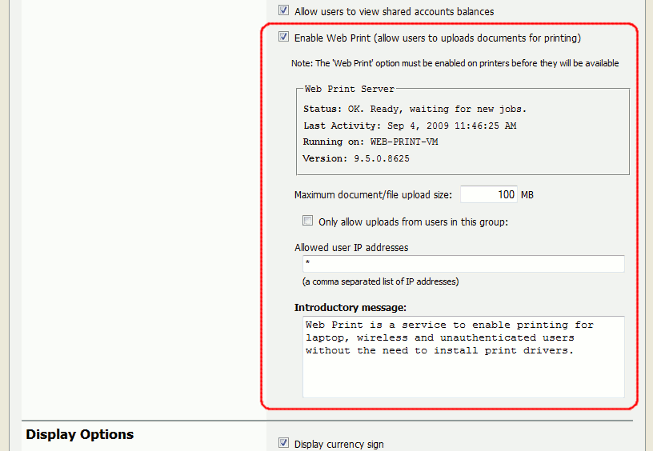
Enable Web Print (allow users to uploads documents for printing) | When enabled a Web Print item will appear in the navigation menu of the user web interface, and users will be able to use Web Print functionality. When disabled this item will not be visible and Web Print functionality will not be available to users. |
Maximum document/file upload size | If a user uploads a document greater than the specified size (in MB) their upload will be rejected. |
Only allow uploads from users in this group | This option may be used to restrict Web Print access to a particular group of users. When this option is enabled users not in the specified group will not see the Web Print item in the navigation menu. |
Allowed user IP addresses |
This option may be used to restrict Web Print access to a select IP address range. For example, access might be limited to systems on a wireless network (i.e. force users on the wired network to use standard print queues). Address ranges may be entered in the format: |
Introductory message |
This message appears on the first page after a user clicks the Web Print item, and can be used to explain the service, offer site-specific advice or other information to assist the user. HTML is supported, e.g. <p> tags may be used to start a new paragraph, or an <a> tag may be used to provide a link. |
Table 19.3. Web Print Settings
The print options selected during the Web Print wizard are currently limited to the number of copies to print. Other print options such as grayscale, duplex, paper size etc. are selected based on the default options on the print queue.
If it is important to provide the user with a print option choice, e.g. when the same printer has trays for
Letter and Legal paper, two print queues may be created and set up with different default settings. E.g. one
print queue called Library Printer (Letter) that defaults to the Letter size and tray, and
a second print queue (pointing to the same physical printer) called Library Printer (Legal)
that defaults to the Legal size and tray.
Note
The developers hope to be able to support grayscale and duplex print options in the near future.
Part of the Web Print wizard involves selecting the target printer from a list. This is fine most environments, but organizations with many printers or large sites may prefer something that provides users with more context about the printer they are selecting.
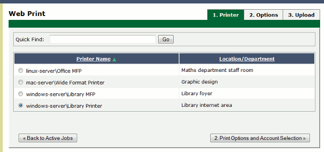
Figure 19.15. Web Print: selecting a printer from the list, which may be replaced with a map or custom list
Using a graphical map can assist users to find the most convenient printer. A map allows a user to select a printer by location, rather than guessing the printer's location based on its name. Using printer maps or other types of custom printer lists in PaperCut NG does not require any special or proprietary software - they can easily be implemented using open standards and free software.
Custom content is loaded in place of the printer list by placing the appropriate file at
[app-path]/server/custom/web/ as described in the following table:
| File Name | Description |
|---|---|
| If this file exists it will be loaded as an HTML page and displayed in an iframe in place of the printer selection list. The HTML may contain any content or images including links to other pages (which will also be loaded in the iframe by default). |
| If this file exists it will be loaded as a SVG page and displayed in an iframe in place of the printer selection list. The SVG may contain links to other pages or other SVGs. An SVG may be created using software such as Microsoft Visio or the free/open source Inkscape, and is a convenient way of displaying a map or floor plan with clickable links. |
Table 19.4. Files used for custom printer selection in the Web Print wizard
Tip
Any custom content placed in [app-path]/server/custom/web/, such as additional images,
can be accessed via a URL beginning with /custom/. For example if a file named
floor-plan.png is placed in [app-path]/server/custom/web/ it can
be accessed via the URL /custom/floor-plan.png.
Tip
The custom printer map is displayed in an iframe with dimensions 776px x 400px. If the content is larger than this then scrollbars will be visible (the area will not be expanded to fit the content).
This example runs through the process of creating a printer map using HTML with image maps. This method is most suitable if you have floor plan images and/or arial photos of your site (e.g. in PNG or JPEG format). If you have a plan in SVG/vector graphic format then the section called “Example 2: Creating a Printer Map Using SVG” may be more suitable.
The source for this example can be found at
[app-path]/server/examples/printer-maps/html-image-map/.
For this example we will create a printer selection map with two layers: a site plan and floor plans. Users first choose a building from the site plan, then choose a printer from the building's floor plan. We have two buildings: Building A and Building B. Each building has one floor of interest with identical floor plans and five selectable printers.
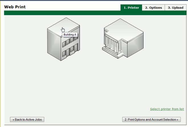
The first step is to create a file named
printer-map.htmlat[app-path]/server/custom/web/. This file will be loaded as an HTML page in an iframe in place of the default printer selection list, and may contain any content you choose, including links to further pages. Open this file in a text editor.We then add the site plan image:
<img src="site-plan.png" usemap="#buildings"
     style="width: 422px; height: 190px; border: none;" />
The
usemap="#buildings"attribute tells the image to look for an image map with the namebuildings. Image maps allow you to make parts of an image "clickable". For more information about the HTML<map>element see xhtml.com's map element reference.Now we define the image map.
<map name="buildings">
  <area shape="poly" coords="" href="building-a.html"
        alt="Building A" title="Building A" />
  <area shape="poly" coords="" href="building-b.html"
        alt="Building B" title="Building B" />
</map>
Here we have defined a new image map called
buildingswith two clickable areas. These areas are polygon shapes (shape="poly"), which means we can specify a list of points that will form the outline of the clickable area (i.e. the area inside the points will be clickable).Clicking the first area will load the page
building-a.html. Thealtandtitletags provide information about the link and display a tooltip when the user hovers over the area.We have defined two areas and the pages they will link to but we have not yet defined the coordinates for these areas. This is done using the
coordsattribute of the twoareatags. Using an image editor we can find coordinates for the outline of the two areas. Most image editors, including MS Paint, display pixel coordinates when hovering the mouse over the image.Using the image editor we find the following points for Building A (the lefthand building), starting from the top left corner, in
(x,y)format:(0,48), (84,0), (143,34), (143,142), (60,190), (0,155). Pixels are counted from the top left corner of an image, so the coordinate(60,190)means "60 pixels from the top, 190 pixels from the left".We repeat the previous step for the second building to get coordinates similar to:
(242,50), (320,4), (422,63), (422,135), (332,190), (226,131).Now that we have the clickable area coordinates we can define them in our image map.
The definition for the
areatag when using apolytype shape tells us that the coordinates are specified in a list of x,y coordinates (i.e. "x1,y1,x2,y2...xn,yn"), so we enter the coordinates in thecoordsattributes as follows:<map name="buildings"> <area shape="poly" coords="0,48,84,0,143,34,143,142,60,190,0,155" href="building-a.html" alt="Building A" title="Building A" /> <area shape="poly" coords="242,50,320,4,422,63,422,135,332,190,226,131" href="building-b.html" alt="Building B" title="Building B" /> </map>Opening
printer-map.htmlin a web browser should now display the site plan image. Hovering the mouse over each building should display the link cursor and indicate a link to the respective pages.The next step is to create the
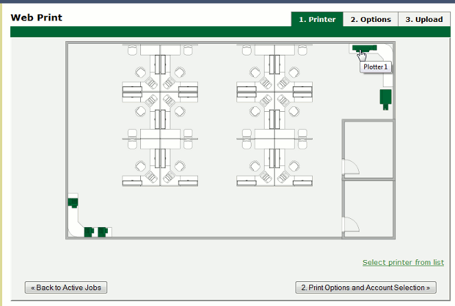
building-a.htmlpage. Using a similar process to the existing page we addfloor-plan.pngand create an image map for it:<img src="floor-plan.png" usemap="#printers" style="width: 600px; height: 362px; border: none;" /> <map name="printers"> <area shape="rect" coords="4,289,22,307" href="" alt="building-a\Printer 1" title="building-a\Printer 1" /> <area shape="rect" coords="33,342,51,360" href="" alt="building-a\Printer 2" title="building-a\Printer 2" /> <area shape="rect" coords="58,342,76,360" href="" alt="building-a\Printer 3" title="building-a\Printer 3" /> <area shape="rect" coords="521,7,566,23" href="" alt="building-a\Plotter 1" title="building-a\Plotter 1" /> <area shape="rect" coords="571,88,592,129" href="" alt="building-a\MFP 1" title="building-a\MFP 1" /> </map> <div>Building A (<a href="printer-map.html">back</a>)</div>This map is mostly similar to the previous one, except that we have defined five rectangle shapes (
shape="rect") and provided a link back to the main site plan (printer-map.html).Rectangle shapes in an
<area>element are defined with the coordinates of top left and bottom right corners ("x1,y1,x2,y2").Now we have the images and shapes in place for the site plan and one building's floor plan. To finish off this building we now need to define what happens when each printer is clicked. This is done using a JavaScript function
selectPrinter. CallingselectPrinter('my-server', 'Library Printer')will submit the form on this step of the Web Print wizard, selecting the printer calledLibrary Printer, hosted on the print server calledmy-server.We can call this JavaScript function when one of the defined areas is clicked by setting the
hrefattribute as follows:<area shape="rect" coords="4,289,22,307" href="javascript:parent.selectPrinter('building-a', 'Printer 1');" alt="building-a\Printer 1" title="building-a\Printer 1" />Repeat the previous step for the remaining printers, taking care that the server and printer names are entered correctly. Note that the printer name is the printer's unique name on the print server, and may be different to the printer's "share name".
Repeat the steps to create
building-a.htmlto createbuilding-b.html(or simply copy the file and modify to suit).Test the Web Print wizard to ensure that clicking on a building takes you to that building's floor plan, and clicking on a printer submits the form to select that printer. Note that if the names you've used for the printers don't actually exist in your PaperCut NG server then you'll see an error message about the printer not being available. You may like to modify the details for one of the printers to match a real printer so that the wizard can be tested end-to-end.
The source for this example contains some additional tweaks to improve browser consistency, such as removing the border and white background of the iframe in Internet Explorer.
This example explains how to use an SVG image for a clickable printer map. This method is most suitable if you have plans or drawings in a vector format that can be saved as SVG. Otherwise the section called “Example 1: Creating a Printer Map Using an HTML Image Map” may be more suitable.
An example SVG floor plan with clickable printers can be found at
[app-path]/server/examples/printer-maps/html-image-map/.
Modern web browsers are capable of displaying an SVG file in a similar way to displaying a web page. Mozilla Firefox and Opera can display SVGs "out of the box", and Microsoft Internet Explorer can display SVGs using the Adobe SVG Viewer add-on. In addition to drawing the image parts of the image may be made "clickable" to provide links to other pages or, as in this case, to call a JavaScript function that selects a printer.
In this example we will describe how to take an existing SVG image and make parts of it clickable so that a printer may be selected.
Tip
A Microsoft Office Visio drawing can be saved as SVG and used in this example.
Download and install Inkscape, the free/open source vector graphics editor, and use it to open your SVG.
Select the object that should be made "clickable". You should see a dotted background around the object.
Right-click the object and select Create Link.
Right-click the object and select Link Properties.
In the Link Properties dialog that appears, enter a value for the Href field like:
javascript:parent.selectPrinter('server', 'printer');, whereserveris the name of the print server andprinteris the name of the print queue.Repeat to create links for each printer in the image.
Select → and choose a file type of
Plain SVG (*.svg). Save the image to[app-path]/server/custom/web/printer-map.svgon the PaperCut NG server.Try the Web Print wizard to test. The SVG should be visible on the first step of the Web Print wizard in place of the printer list. Clicking a print should move on to the next step.
The following advanced configuration options are available via the config editor. See the section called “Using the Config Editor” for information about using the config editor.
| Config Name | Description |
|---|---|
web-print.job-idle-timeout-mins |
If a Web Print job remains unchanged for longer than this period of time it is considered finished and is "cleaned up". The document and associated files are removed, and the job will no longer appear in the user's list of current Web Print jobs. The default idle job timeout is 20 minutes. |
web-print.job-rendering-timeout-mins |
The Web Print server is given this length of time to render a Web Print document. If a print job has not been generated from the document after this time the job is marked as errored and associated files are removed. The default job rendering timeout is 5 minutes. |
web-print.max-copies | This is the maximum number of copies a user may print via Web Print. This option exists to prevent users accidentally (or thoughtlessly!) printing too much. |
web-print.hot-folder |
When a user uploads a file via the Web Print interface is it written into the "hot folder" along with
a |
Table 19.5. Web Print Config Editor Keys
The following configuration options are available in the Web Print server configuration file, located at
[app-path]/providers/web-print/[platform]/web-print.conf.
| Config Name | Description |
|---|---|
hotfolder | The location of the Web Print hot folder. This is generally a mapped drive letter (Windows) or a mount point that maps to a file share (Mac, Linux). It may also be a local path, if the Web Print server software is running on the same system as the PaperCut NG primary server. |
debug |
Set to |
Table 19.6. Web Print Server Config File